Our pellet extruder was developed in house following several sources online. Particularly, we looked at
Bartlett's RC4 video.
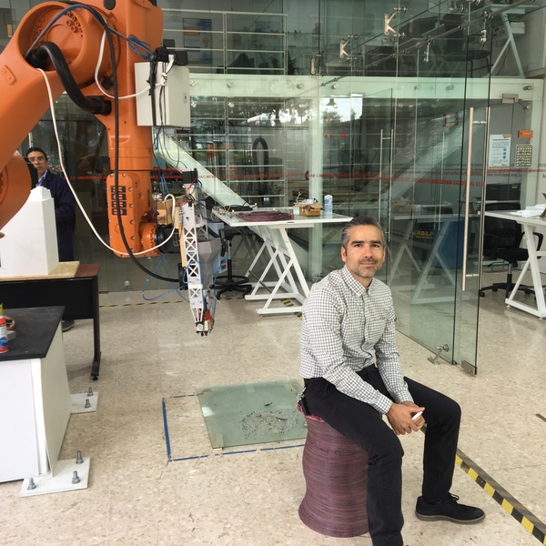
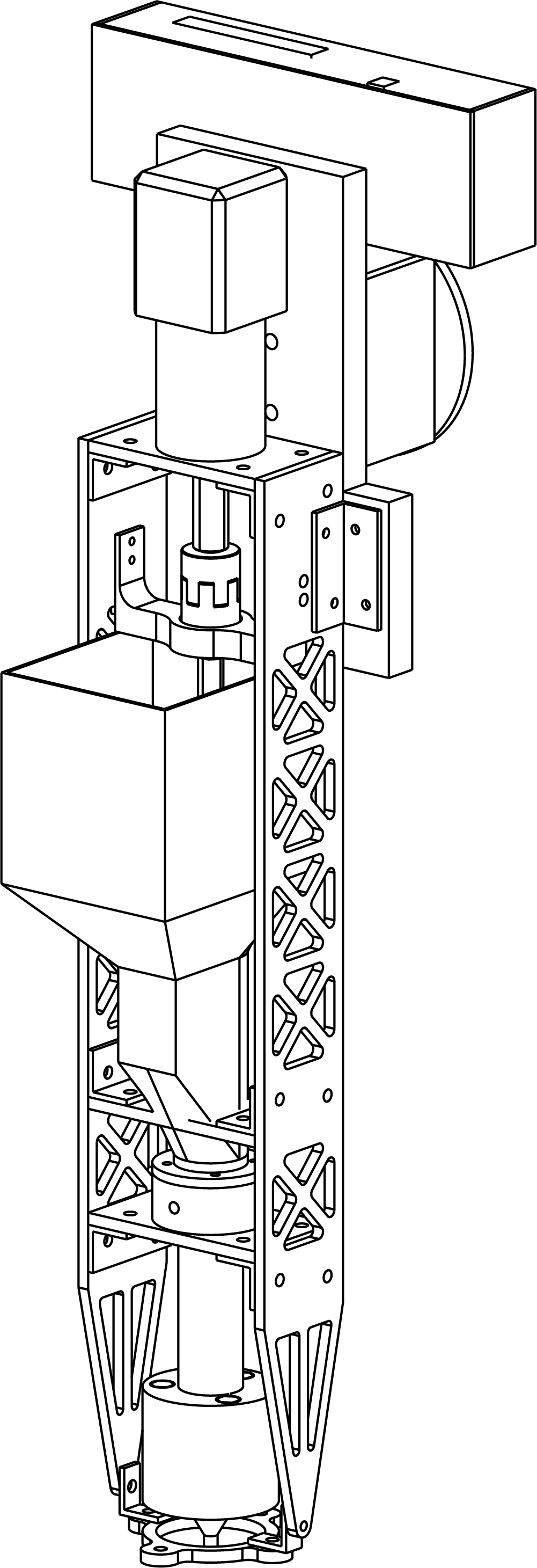
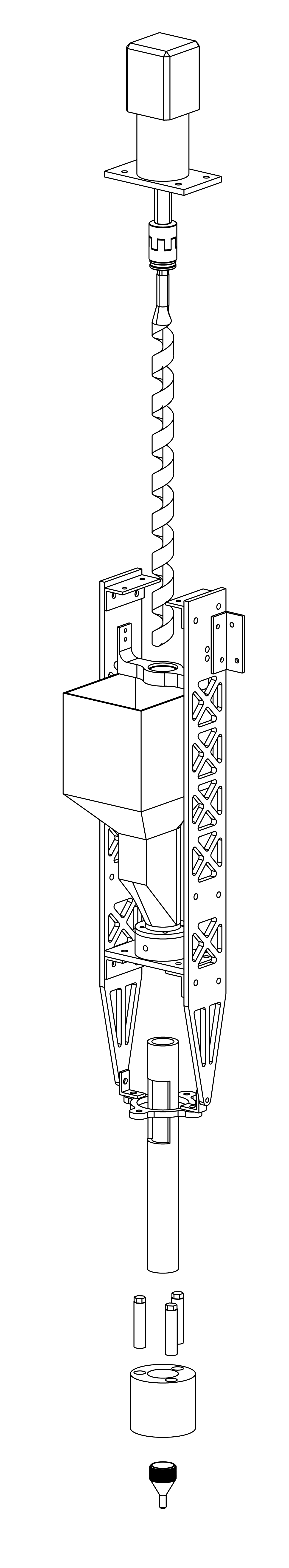
The design features a 1" auger in a tube, with a 3d printed tumbler, and a NEMA23 motor with a planetary gearbox. The heat block is made of three 75 watt heat elements, that are controlled using a REX C100 PID controller. We are also using a heated bed using 15m of low temp nichrome coil-wire. The whole thing is held together with an aluminium chasis and attached to a KR30 or KR10 Robot. We are printing ABS and PLA. In the case of PLA, it is printed from reclaimed suppert material and reused plastic, ABS is store-bought,
The device is attached to the kuka flange with M10 screws. This is an image that we used to design the attachment which is made out of plywood: back to top
The printing
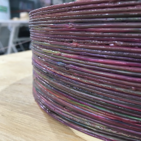
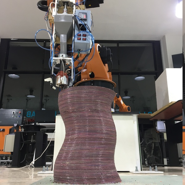
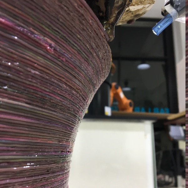
PLA large format prints
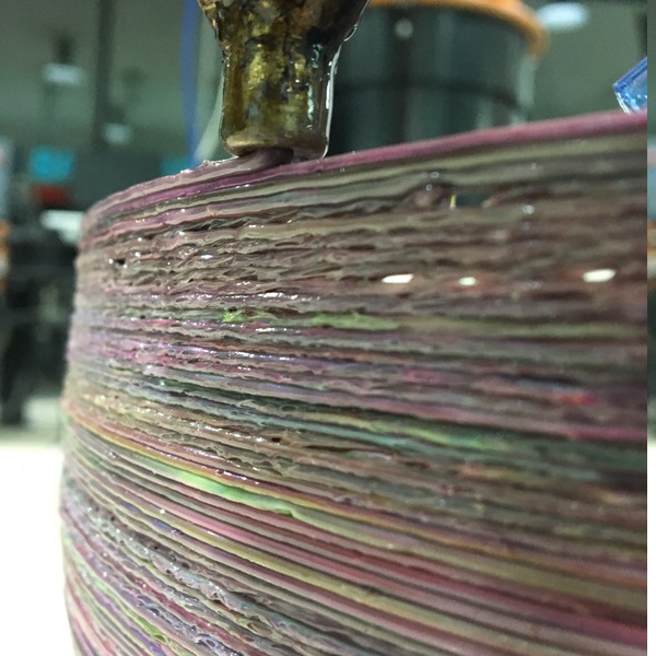
We have printed with PLA and ABS, in the case of PLA the prints are not as consistent because we are recycling plastic and that pellet is not consistent.
This is our first furniture piece, which was made of recycled PLA.
Even though this was not part of the assignment, we wanted to showcase this in the review time for week 5 because we wanted to share how recycling waste from other printer is a great thing to do in fablabs.
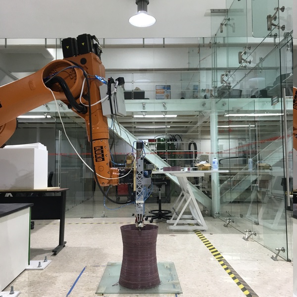
The Machine in Action
The extruder attached to robots
The extruder can be attached to any robotic arm with a min payload of 6kg. We have been working on ways to connect the digital outputs of the robotic arm to the arduino that controls the stepper in order to have more freedom in our prints. Thanks for watching!
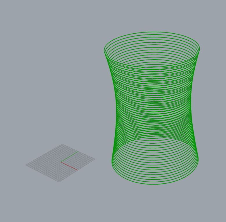
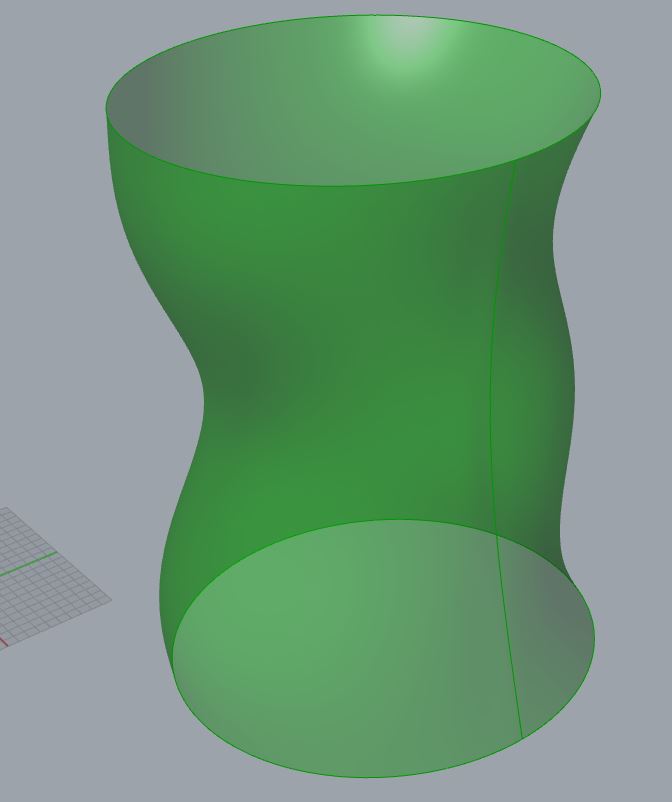
The stool was made from a parametric model in grasshopper. It has two stages: first, creating the shape, and then creating the toolpath commands in KRL (kuka robot language) which is kuka's version of G-code.
The shape is an array of circles in the z direction, scaled subtly and moved around on the XY plane. This gives the stool its distinctive shape.
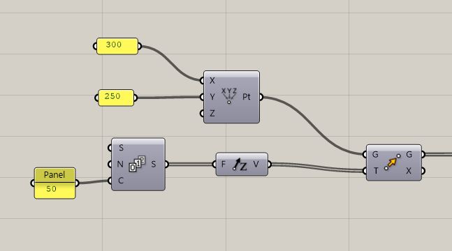
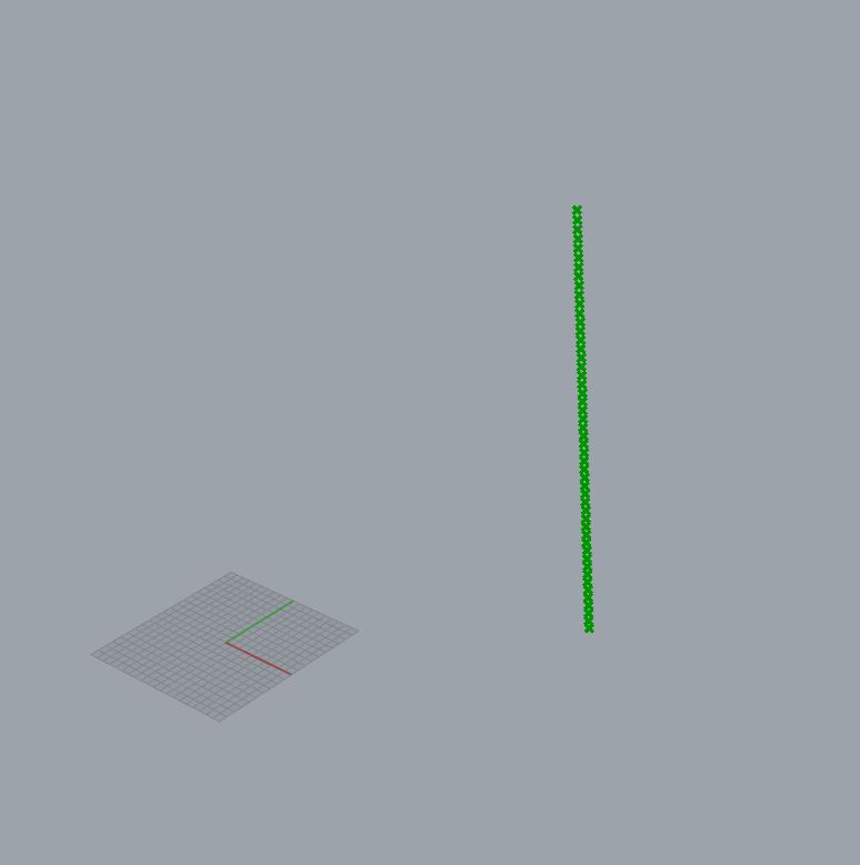
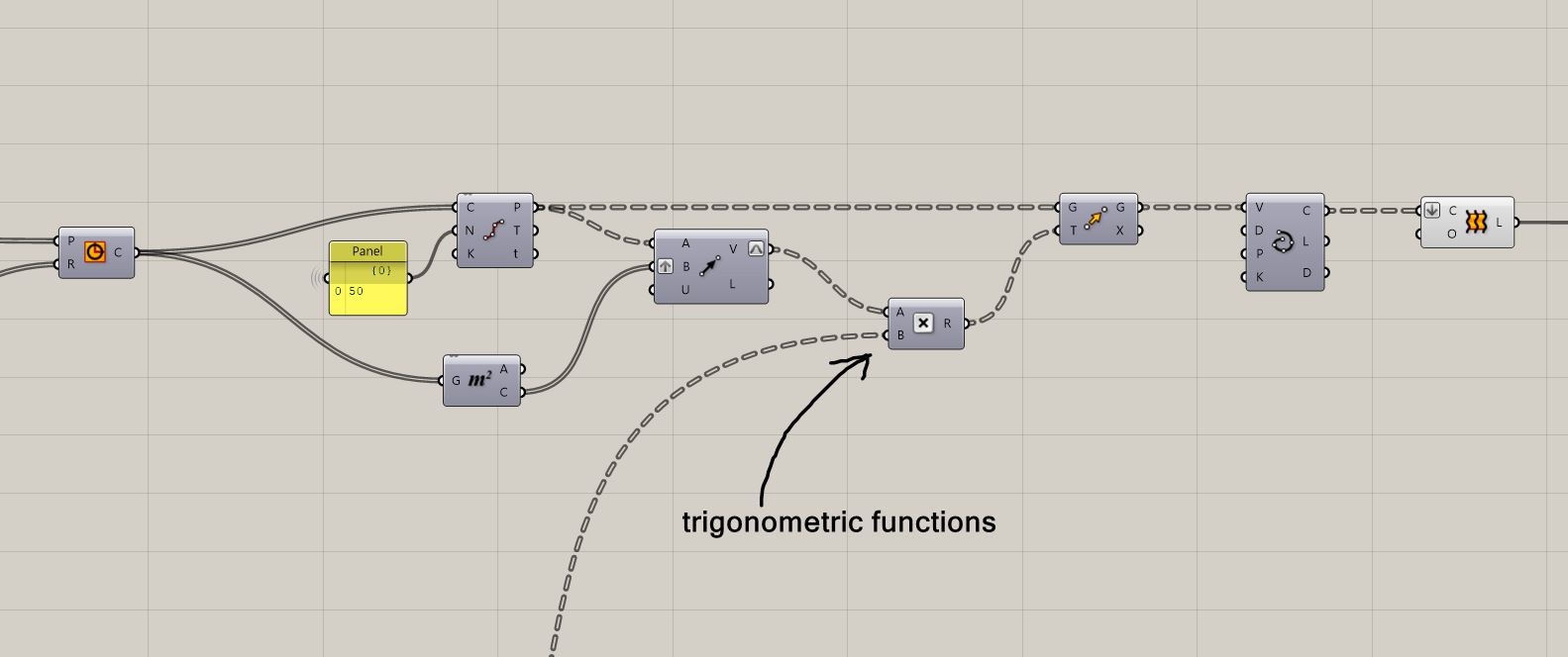
The first step is to create an array of points that will be all the circle centers.
To create these points, I just created a single point at {300,300,0} and then moved it up using a series component that drives a Z vector component. The series component creates a series of numbers, I configured the step to 10mm and the count to 50.
Then I created the circles using the points as centers. However, to create the radii, I had to create a range component that drives a graph mapper. The range component outputs 50 numbers between 0 and 1, and the graph mapper maps these numbers graphically using that graph wodget to a new range, in this case 0 to 180mm.
After that, I divided each circle in 50 segments using the divide curve command.
This gives me a tree structure, with each branch being a list of 50 points, on per original circle.
Each of these points will be moved with a vector created from the center of each circle to the point itself; it will be moved radially from the center. However, the vector itself will be scaled according to some trigonometric functions.
The trigonometric functions basically are just the multiplication of two sines accoridng to the points position in the list.
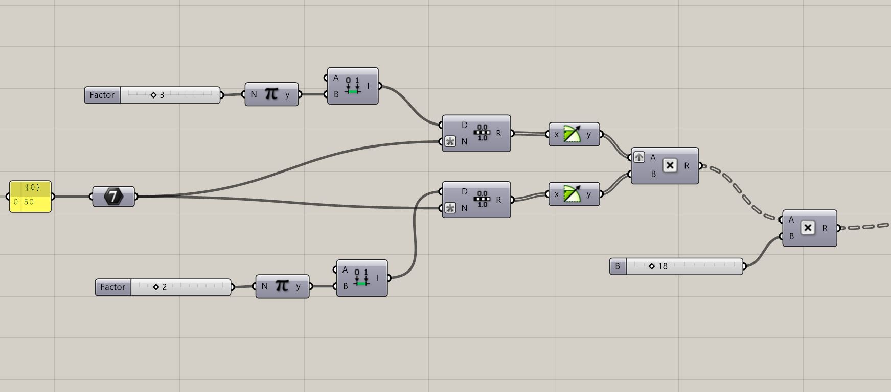
Basically the expression is this:
sin(A) x sin(B)
Where A is betwen 0 and 3*Pi and is the same for each circle.
and B is between 0 and 2*Pi and changes with each point.
The resulting list is actually 2500 values, which is 50 times 50. This is because we have 50 original circles, then we are dividing each one in 50 points.
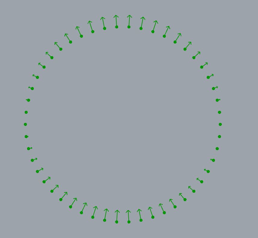
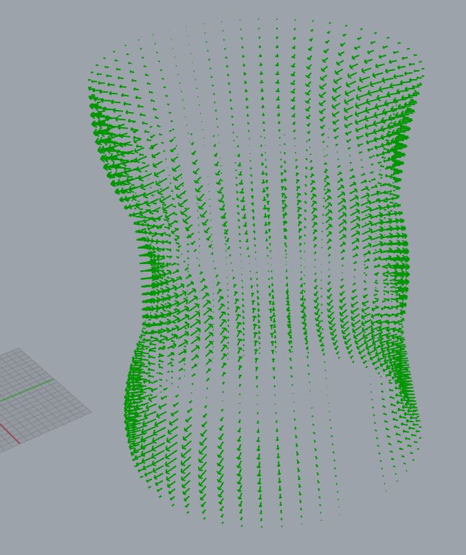
Here is an image of a single circle's points and their motions:
When every point moves using this maths it looks like this.
After that I recreate the curves and loft them to get the stool's shape.
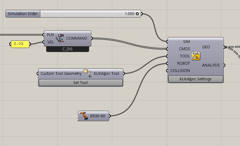
Toolpath generation of KRL with Kuka PRC
Kuka PRC is a grasshopper plugin that allows to create KRL text files to run on any kuka robotic arm. It is mantained by The associaction for Robots in Architecture, based in Austria, and is a very easy to use tool.
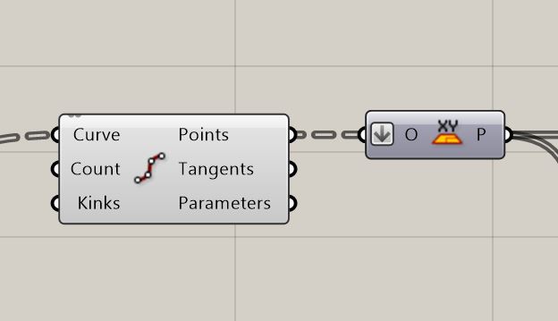
The tool path is created from the shape. First I contour it at the layer height in this case 1.25mm. Then, I take each contour and divide it into points. In this case each contour is divided into 200 points.
After that I create a simple XY plane on each point. This is the plane that Kuka PRC takes to create the commands.
The list of planes is fed to PRC's LIN command which basically tells the robot to move the tool to that point. The robot will also orient the tool to the Z component of each plane, but in this case, the tool is upright, because we are extruding vertically always. This is why we have an XY plane.
I configured the speed to 0.02 m/s.
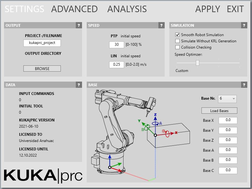
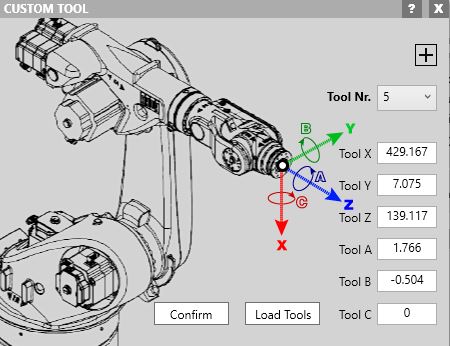
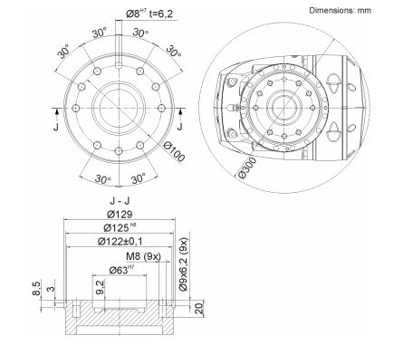
Also, you have to tell PRC which robot you are using, and which tool you are using. You have to measure the tool physically to input the values from the robot.
These are the tool's values:
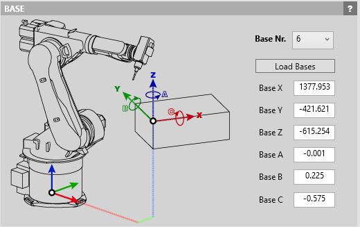
After that, you configure the base, which in this case is this:
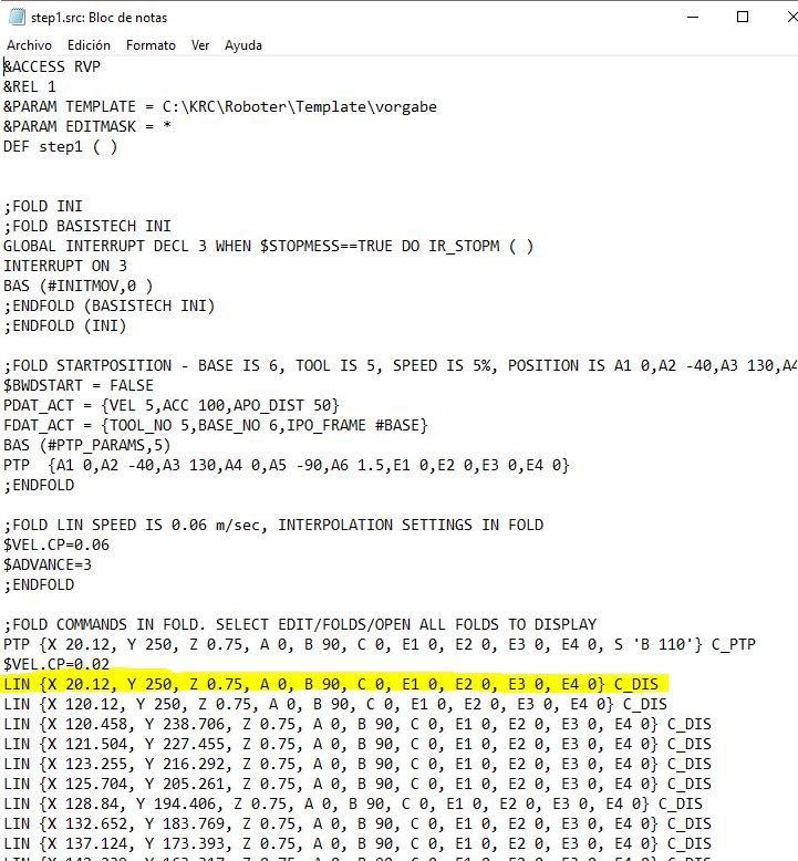
Once you do all that, PRC will save an *.src file that you can view on notepad:
Basically, each plane on the original list is then translated to a line with X, Y, Z values, but also A, B, C values. X, Y and Z are the position of each point, and the robot will move to that position at the configured speed. A,B, and C are the orientation values for the tool, rotations around Z, Y, and X axes.
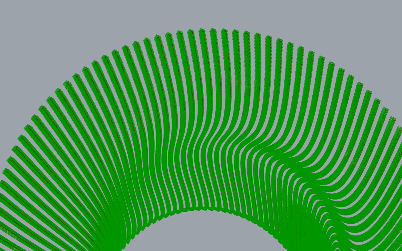
After that, you can preview an animation of the robot's toolpath:
To load up the porgram onto the robot, you put in a USB and plug it in, then you just run it, and the robot does its magic.
 back to top